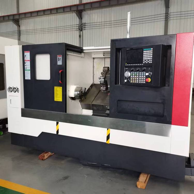
How to troubleshoot the CNC lathe?Common faults and troubleshooting of CNC lathes
CNC lathe is a technically complex mechatronic lathe, and the causes of its failures are generally more complicated. In order to facilitate the analysis and troubleshooting, according to the different parts of the CNC lathe, it is divided into two categories.
- Host failure
The host part of the CNC lathe mainly includes machinery, lubrication, cooling, chip removal, hydraulic pressure, pneumatic and protective devices. Common host failures include: mechanical transmission failures caused by improper mechanical installation, debugging and operation, and excessive friction of guide rail movement. Faults are characterized by large transmission noise, large running resistance, and low machining accuracy. For example: the flexible coupling of the axial transmission chain is loose, the gears, screw and bearings are short of oil, the guide rail plug iron is not adjusted properly, the guide rail is poorly lubricated, and the system parameters are set improperly and other reasons can cause the above faults. In addition, the failure phenomena of hydraulic, lubrication and pneumatic systems are mainly manifested as pipeline blockage and poor sealing. When the main engine fails, if the failure is within the normal maintenance range of the operator, the operator will solve it by himself; if the failure is serious, professional maintenance personnel must be invited to repair it. - Electrical failure
Electrical faults are divided into weak current faults and strong current faults. The weak current part mainly refers to CNC devices, PLC controllers, CRT monitors and Dong clothing sheets
Elements, electronic circuits such as input and output devices, this part can be divided into hardware failures and software failures. Hardware failure mainly refers to the above-mentioned devices
Failures of integrated circuit chips, discrete components, connectors, and external connection components on printed circuit boards. Common software faults include: processing program error, system program and parameter change or loss, computer operation error, etc. The strong current part refers to electrical components such as relays, contactors, switches, fuses, power transformers, motors, electromagnets, travel switches and the circuits composed of them.
(1) Electrical failure on the main body of the lathe
For this part of the fault, you can first use the alarm number of the lathe self-diagnosis function to prompt, read the ladder diagram or check the signal status of the I/0 interface, and combine the drawings, materials, troubleshooting flow charts, and adjustment methods provided by the lathe maintenance manual. Personal experience checks for failures. For example, hardware overtravel in the forward or reverse direction of each motion axis. This type of failure is mostly caused by the overtravel movement of the lathe pressing the hardware limit switch. Generally, refer to the maintenance manual of the lathe and the control system, and manually move in the opposite direction of the alarm direction to release it. Press the “RESET” button, the fault alarm display is cleared.
(2) Servo amplification and detection of some faults
For this part of the fault, you can use the alarm number of the self-diagnosis function of the computer, the information status of the computer and the servo amplifier driver board to read the fault alarm indicator light, refer to the waveform and voltage value of the key test points introduced in the maintenance manual, computer, The setting of the relevant parameters on the servo amplifier board, the setting of the short-circuit pin and the adjustment of the relevant potentiometer, and the replacement of the function compatible board or the spare board can be solved.
(3) Partial failure of the computer
This part of the fault is mainly based on the alarm number of the computer self-diagnosis function, the information status indicators of each board of the computer, the waveform and voltage value of each key test point, the adjustment of each related potentiometer, the setting of each short-circuit pin, and the setting of the parameter value of the lathe. Settings, special diagnostic components, refer to the computer control system maintenance manual, electrical atlas, etc. to exclude. Users should pay full attention to these technical software when purchasing CNC lathes, and manufacturers should pass on some commonly used and necessary software diagnostic techniques to users to master.
(4) AC spindle control system failure
When the AC spindle control system fails, you should first check whether there has been any accidental operation that does not comply with the operating procedures, whether the power supply voltage has experienced transient abnormalities, and perform visual inspections to see if there are intuitive and easy-to-check faults such as circuit breaker tripping and fuse disconnection. If there are no above problems, then confirm whether it is a fault with alarm display or without alarm display. And according to different situations, be dealt with separately.


